


| Price | 5.5~10USD/PC |
| MOQ | 1000PCS |
| Delivery Time | 2 Weeks |
| Place of Origin | CHINA |
| Model Number | CA30 Type |
| Packaging Details | Bulk |
| Payment Terms | T/T, Western Union |
| Supply Ability | 1000,000PCS Per Month |
| Place of Origin | CHINA | ESR | 2.5 Ohm |
| Packaging Details | Bulk | Tolerance | ±10% |
| Voltage - Rated | 50V | Model Number | CA30 Type |
| Mounting Type | Through Hole | Size / Dimension | 8x22mm |
| Supply Ability | 1000,000PCS Per Month | Name | Tantalum Capacitors |
| Payment Terms | T/T, Western Union | Type | Hermetically Sealed |
| Package / Case | Axial | Price | 5.5~10USD/PC |
| Delivery Time | 2 Weeks | Minimum Order Quantity | 1000PCS |
| Capacitance | 120uF | Operating temp | -55°C ~ 125°C |
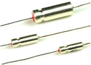
VISHAY 109D127X9050F2 Cross CA30 Type Non-Solid Wet Tantalum Capacitors 120UF 10% 50V AXIAL For Operation to +125 °C
Manufacture Supply CA30 Series 125C Axial-lead Tantalum Electrolytic Capacitor
The CA30 type non-solid electrolyte fixed tantalum capacitor adopts tantalum powder as the positive electrode and the silver outer shell as the negative electrode. The axial lead-out structure has excellent electrical properties and cost performance.

Applications
Suitable
for
DC
or
pulsating
circuits
of
military
and
civil
electronic
equipment
such
as
weapons,
communications,
and
submarine
cables.
It
functions
as
a
direct
communication
and
energy
storage.
Silver
case
encapsulation,
Epoxy
end-filled,
Tubular,
Axial-lead,
with
insulation
sleeve,
Heteropolarity
Stable
in
Electrical
performances,
High
Reliability,
Low
DCL,
Long
life-span,
Testing
standard
is
superior
to
SJ/T10030-91
Standard,
Small
size,
Convenient
for
Installation.
Applying
in
Communications,
Instruments
and
Meters,
such
Electrical
Equipment
with
DC&
Impulse
circuit
HF and VHF for RF circuits

Dimension (mm)

Specifications
| Standard | l SJ/T10030-91 |
|
Operating temp range |
l -55℃~+125℃ |
| Rated voltage | l 50V |
|
Derating voltage |
l 30 V |
|
Capacitance tolerance |
l K - ±10% |
| Model |
Spec V-μF |
Standard |
Dimension mm |
d mm |
+20℃ Loss % |
+20℃ Leakage current μA |
| CA30 | 50-120-±10% | SJ10030-91 | Ф8*22 | 0.8 | 30 | 6 |
Features
Silver case package, semi-sealed, cylindrical, axially led out.
Polarity, stable and reliable electrical performance, large volume capacity, high working voltage and minimal leakage current.
Axial through-hole terminations: standard tin /lead (SnPb), 100 % tin (RoHS-compliant) available
Technical Characteristics
Operating
Temperature
Range:
-55C~+125C
DC
Leakage
at
25C:Ⅰ0≤0.001CRUR
(μA)
or
1μA
DC
Leakage
at
85C
or
125C:Ⅰ0≤0.008CRUR
(μA)
or
8μA
Capacitance
Tolerance:
K:
±10%;M:
±20%
Capacitance
Range:
0.47uf~3300uf
Voltage
Range:
6.3V~125V
Rated
Voltage:
6.3V,
10V,
16V,
25V,
40V,
50V,
63V,
75V,
100V,
125V
Capacitance
with:
0.47uf,
0.68uf,
1.0uf,
1.5uf,
2.2uf,
3.3uf,
4.7uf,
6.8uf,
10uf,
15uf,
22uf,
33uf,
47uf,
68uf,
100uf,
150uf,
220uf,
330uf,
470uf,
680uf,
1000uf,
1500uf,
2200uf,
3300uf.
Precautions
*It is forbidden to use a multimeter to measure tantalum capacitors (it is easy to cause irreversible damage and lead to product scrapping).
*The measurement frequency of capacitance and loss tangent is 100Hz, DC bias voltage U-=2.20 -1.0V, AC bias U~=1.00 -0.5V (effective value); the measurement method is series equivalent circuit.
*Test leakage current above 85 °C, and apply derating voltage.
PERFORMANCE CHARACTERISTICS
Operating
Temperature:
-55
°C
to
+85
°C (to
+125
°C
with
voltage
derating)
Capacitance
Tolerance:
at
120
Hz,
+25
°C.±
20
%
standard.
±
10
%,
±
5
%
available
as
special.
DC
Leakage
Current
(DCL
max.):at
+25
°C,
+85
°C,
+125
°C:
leakage
current
shall
not
exceed
the
values
listed
in
the
Standard
Ratings
tables.
Life
Test:
capacitors
are
capable
of
withstanding
a 2000
h
life
test
at
a
temperature
of
+85
°C
or
+125
°C
at
the applicable
DC
working
voltage.
Following
the
life
test
1.
DCL
shall
not
exceed
the
initial
requirements
or
1
μA, whichever
is
greater.
2.
The
ESR
shall
meet
the
initial
requirement.
3.
Change
in
capacitance
shall
not
exceed
10
%
from
the initial
measurement.
For
capacitors
with
voltage
ratings of
15
VDC
and
below,
change
in
capacitance
shall
not exceed
+
10
%,
-
25
%
from
the
initial
measurement.