| Price | Negetiable |
| MOQ | 1000PCS |
| Delivery Time | 7 working days |
| Brand | UCHI |
| Place of Origin | Dongguan,Guangdong,China |
| Certification | ROHS,ISO |
| Model Number | IT |
| Packaging Details | Bulk |
| Payment Terms | T/T Paypal |
| Supply Ability | 50000000PCS per month |
| Dissipation factor | Approx. 0.7 mW/°C(in air) | Operating temperature range | -30 ~ 110 °C |
| Thermal time constant | Approx. 5.0 s : 3.5 mW : -30 ~ 110 (in air) | Place of Origin | Dongguan,Guangdong,China |
| Packaging Details | Bulk | Model Number | IT |
| Supply Ability | 50000000PCS per month | Certification | ROHS,ISO |
| Brand Name | UCHI | Payment Terms | T/T Paypal |
| Brand | UCHI | Price | Negetiable |
| Delivery Time | 7 working days | Minimum Order Quantity | 1000PCS |
| Rated zero-power resistance | 10 KΩ ± 1 % (at 25°C) | Maximum power rating | 3.5 mW : -30 ~ 110 (in air) (at 25°C) |
Negative
Temperature
Coefficient
Thermistor
Operating
Temperature
Range
-30
~
110
°C
Scope
This
specification
defines
ratings,
dimension,
insulation,
climatic
test
and
mechanical
characteristics
for
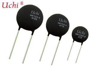
MJT
type
thermistor
Climatic
test
Dry Heat
After
the
test
samples
are
exposed
in
air
at
90±1°C
for
1,000
hours,
the
change
ratio
of
the
rated
zero-power
resistance
shall
be
within
±1%
of
the
initial
value.
Damp heat
After
the
test
samples
are
exposed
in
the
humidity
of
95%
at
40±2°C
for
1,000
hours,
the
change
ratio
of
the
rated
zero-power
resistance
shall
be
within
±1%
of
the
initial
value.
Cold
After
the
test
samples
are
exposed
in
air
at
–30±1°C
for
1,000
hours,
the
change
ratio
of
the
rated
zero-power
resistance
shall
be
within
±1%
of
the
initial
value.
Loading
After
DC
1mA
current
is
applied
to
the
test
samples
in
the
temperature
of
40±2°C
and
the
humidity
of
95%
for
1,000
hours,
the
change
ratio
of
the
rated
zero-power
resistance
shall
be
within
±1%
of
the
initial
value.

Mechanical
characteristics
1.
Resistance
to
soldering
heat
The
terminals
shall
be
dipped
in
to
a
soldering
bath
having
a
temperature
of
260±5°C
to
a
point
2.0
mm
from
the
body
and
then
be
held
there
for
5
±1s,
the
change
ratio
of
the
rated
zero-power
resistance
shall
be
within
±1%
of
the
initial
value.
2.
Solderability
After
dipping
the
terminal
to
a
depth
in
a
soldering
bath
of
235±5°C
for
2
±0.5s .Approximately 90% of terminals should be covered with solder
uniformly.
3.
Free
fall
After three times fall to a maple board from 0.75 m high, there shall be no visible damage and the change ratio of the rated zero-power resistance shall be within ±1% of the initial value.
4.
Robustness
of
terminations
After
1N
loading
weight
for
10
±
1s
was
applied
to
the
wire
terminations,
there
shall
be
no
visible
damage
and
the
change
ratio
of
the
rated
zero-power
resistance
shall
be
within
±1%
of
the
initial
value.