| Price | Negotiatable |
| MOQ | 1 set |
| Delivery Time | 25 days |
| Brand | HongCe |
| Place of Origin | China |
| Certification | TUV、ITS、CSA、BV、SGS 、CNAS(cost additional) |
| Model Number | CSH-1 |
| Packaging Details | Plywood |
| Payment Terms | T/T |
| Supply Ability | 15 sets per month |
| Impact energy | Max. 2J | Place of Origin | China |
| Packaging Details | Plywood | Model Number | CSH-1 |
| Supply Ability | 15 sets per month | Certification | TUV、ITS、CSA、BV、SGS 、CNAS(cost additional) |
| The maximum measuring range | 0-2J | Brand Name | HongCe |
| Payment Terms | T/T | Accuracy | 0.01J |
| Delivery Time | 25 days | Price | Negotiatable |
| Diameter pendulum | 20mm | Minimum Order Quantity | 1 set |
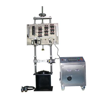
Calibration
Device
For
Spring
Hammer
Calibration
Apparatus
Product
details:
As
the
requirements
shown
in
the
IEC60068-2-75,
this
calibration
device
is
used
to
test
the
impact
energy
of
the
spring
hammer.
It
is
the
special
equipment
for
the
laboratory.
Because it is difficult to measure directly for the offered energy of the calibrated spring hammer, the calibration principle of this device is by comparing the energy which is calculated by the mass of the pendulum and drop height.
The highest resolution capability of this device is 0.01J. The release mechanism is improved in the design, it can maximum reduce vibration affect on the test when the the spring hammer lease, the pendulum rod and aerospace bearing are made of imported good quality steel, so that to improve the precision and stability of the device.
The highest resolution capability of this device is 0.01J. The release mechanism is improved in the design, it can maximum reduce vibration affect on the test when the the spring hammer lease, the pendulum rod and aerospace bearing are made of imported good quality steel, so that to improve the precision and stability of the device.
Technical
parameters:
| Accuracy | 0.01J |
| The maximum measuring range | 0-2J |
| Impact energy | Max. 2J |
| The weight | Copper weight cover(2J) |
| Guide groove diameter | 51mm |
| Pendulum | Steel |
| Diameter pendulum | 20mm |
| Length pendulum | 635mm ± 2,5mm |
| Pendulum H | 120mm ± 2mm |
| Pendulum D | 20mm ± 0,5mm |
| Pendulum W | 4mm ± 0,01mm |
| The energy loss of the pendulum | <0.002J |
| Release device | Ac. Mechanic |
| Trigger distance | >30mm |
| Reference | IEC 60068-2-75 fig. B1 |
Procedure
for
the
calibration
of
spring
hammers:
B.1 Principle of calibration
The principle of this calibration procedure is to compare the energy provided by a spring hammer, which is difficult to measure directly, to the energy of a pendulum, calculated from its mass and height of fall.
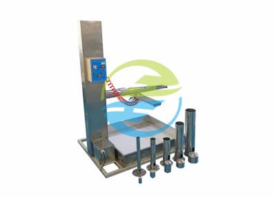
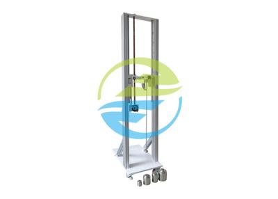
B.2 Construction of the calibration device
The assembled calibration device is shown in figure B.1. Apart from the frame, the main parts are a bearing “a”, a drag pointer “b ”, a pendulum “c”, a release base “d” and a release device “e”.
The main part of the calibration device is the pendulum “c” shown in figure B.2. To the lower end of this pendulum is fixed a steel spring with the details shown in figure B.3. The spring is of spring steel, requiring no special treatment, and is rigidly fixed to the pendulum “c”.
Figure B.4 shows some parts on a large scale
It should be noted that this spring is designed for calibrating spring hammers having characteristics as defined in table 1 for energy values equal to or less than 1 J. For calibrating spring hammers having characteristics as defined for 2 J, the spring of the pendulum of the calibrating device would need to be of a different design.
In order to obtain suitable friction characteristics of the pointer, a piece of thick woven cloth is placed between the metal surfaces of the bearing, the piano wires being bent in such a way that a small force is exerted against the cloth.
Because the release device is removed during the calibration of the calibration device, the release device is fixed to the release base by means of screws.
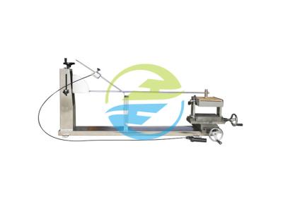
B.3 Method of calibration of the calibration device
The calibration of the calibration device is effected by using a calibration striking element “g” taken from a spring-hammer, as shown in figure B.5. Before calibration, the release device is removed from the calibration device.
The calibration striking element is suspended by four linen threads “h” from suspension points situated in a horizontal plane, 2000 mm above the point of contact between the pendulum and the calibration striking element when the latter is in its rest position. The calibration striking element is allowed to swing against the pendulum and the point of contact under dynamic conditions, point “k”, shall be not more than 1 mm below the point of contact in the rest position. The suspension points are then raised over a distance equal to the difference between both contact points.