| Price | negotiable |
| MOQ | Sample order accepted |
| Delivery Time | 2-5 working days after payment received |
| Brand | SINOMATIC |
| Place of Origin | Shenzhen, China. |
| Certification | CE/ ISO |
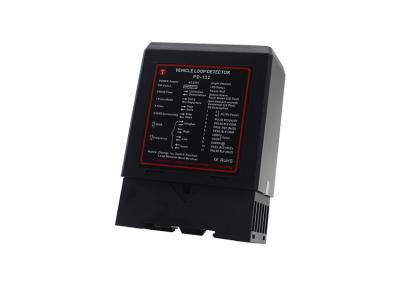
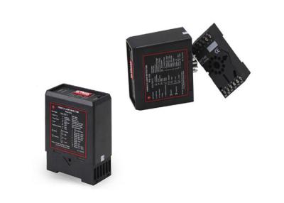
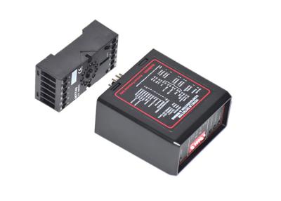
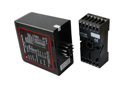
| Model Number | PD-132 |
| Packaging Details | Carton/Plywood box/Pallet |
| Payment Terms | T/T, L/C, D/A, D/P, Western Union, MoneyGram |
| Supply Ability | 3,0000pcs per month |
| Place of Origin | Shenzhen, China. | Packaging Details | Carton/Plywood box/Pallet |
| Reaction Time | 10ms | Model Number | PD-132 |
| Loop connection wiring | Maximum length 200 meters Twisted at least 20 times per meter | Supply Ability | 3,0000pcs per month |
| Certification | CE/ ISO | Voltage available | 220V, 110V, 24V, 12V |
| Brand Name | SINOMATIC | Payment Terms | T/T, L/C, D/A, D/P, Western Union, MoneyGram |
| Model no. | PD132 | Price | negotiable |
| Delivery Time | 2-5 working days after payment received | Product name | PD132 Vehicle Loop Detector |
| Minimum Order Quantity | Sample order accepted | sensitivity | 4 levels |
| Application | Traffic Control System | Operating temperature | -20°C to +65°C |
Detection to Stop Function Vehicle PD132 Loop Detector 24v for Smart Parking System
PD132 loop detector Selling point
PD132 loop detector Function & feature
Application
Technical parameters of Loop Detector
| Net Weight | 300g |
| Dimensions | 78x40x108 mm (L x W x H) |
| Storage temperature | -40°C to +85°C |
| Operating temperature | -40°C to +82°C |
| Autocorrecting time | 1 to 2seconds |
| Loop connection wiring | Maximum length 200 meters,twisted at least 20 times per meter |
| Wiring | Max 50μH to 1000μH (include connecting wiring) Ideal 100μH to 300μH |
| Sensitivity | adjustable in 4 increments |
| Signal holding time | Unlimited / limited when loop is permanently covered 10 minutes |
| Operating voltage | 220v, 110vAC 24v,12vDC |
| Power Consumption | <5W |
| Output relays | 240V/5A AC |
| Frequency range | 20 kHz to 170 kHz |
| Reaction time | 10ms |
Main Features:
1)
Reset
Switch
:
The
reset
switch
enables
the
detector
to
be
manually
reset
during
commissioning
and
testing
.
This
results
in
the
detector
re-tuning
the
sensing
loop
and
becoming
ready
for
vehicle
detection
;
2)
Selectable
Pulse
Time
:
This
feature
sets
the
length
of
time
that
the
pulse
relay
will
be
energized
for
1
Second
or
0.5
Seconds
;
3)
Pulse
Relay
Selection
:
The
Pulse
Relay
may
be
configured
to
energize
on
detection
of
a
vehicle
or
when
the
vehicle
leaves
the
loop
;
4)
Sensitivity
Boost
:
This
feature
sets
the
undetect
level
to
maximum
sensitivity
and
is
used
to
prevent
loss
of
detection
of
high-bed
vehicles
;
5)
Switch
Selectable
Sensibility
:
4
sensitivity
setting
are
available
on
the
switches
to
allow
flexibility
in
configuration
;
6)
Switch
Selectable
Frequency
:
4
frequency
settings
are
available
to
prevent
cross-talk
between
adjacent
loops
;
7)
Filter
Option
:
This
option
is
used
to
provide
a
delay
between
detection
of
the
vehicle
and
switchiing
of
the
output
relay
.
This
relay
is
normally
used
to
prevent
false
detection
of
small
or
fast
moving
objects
;
8)
Permanent
Presence
Option
:
This
feature
ensure
detection
of
the
vehicle
will
be
maintained
when
the
vehicle
is
parked
over
the
loop
for
extended
periods
.


Detail image


Wiring diagram
Operation and Indication
While the detector is tuning, the green Channel LED and red Power LED will be turn on. It remain about 2 seconds, then the green LED turn off. If a loop fault exists the Channel LED will come on and flash indicating a fault. If the fault is self-healing the detector will continue to operate.The green channel LED will also glow whenever a vehicle is detected passing over the inductive loop. The red Power LED at the top of the unit will remain on to indicate that the unit is powered.
Frequency To eliminate interference of two neighbouring wire loops or loop detectors, the frequency can be altered.
Sensitivity The sensitivity of the detector allows the detector to be selective as to the change of inductance necessary to produce an output. There are four sensitivity selections and are set as follows by DIP3 and DIP4 Switch.
Automatic Sensitivity Boost
Automatic sensitivity boost is selected by DIP5 switch on the front of the enclosure and is set as follows: OFF - Disabled, ON – Enabled. Automatic sensitivity boost causes the sensitivity to be boosted to a maximum on detection on the vehicle, and maintained at this level during the presence of the vehicle over the loop. When the vehicle departs the loop and detection is lost the sensitivity reverts to the pre-selected level.